
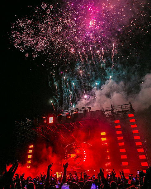
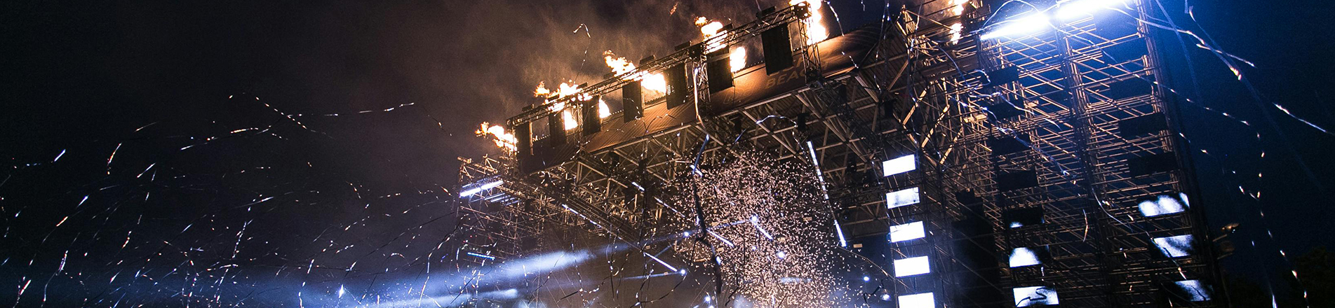
Truss tower systems are widely used at concerts, festivals, exhibitions and other professional events. They allow a horizontal truss beam structure to be positioned above the event area when suitable suspension points are unavailable or when the production requires a temporary ground supported solution.
A complete system combines truss pillars with bases, outriggers, sleeve blocks, top sections, hoists and other compatible components. The truss beams provide the main mounting positions for lighting fixtures, speakers, LED displays and other approved event equipment. The tower system allows these beams to be raised and positioned at the required working height.
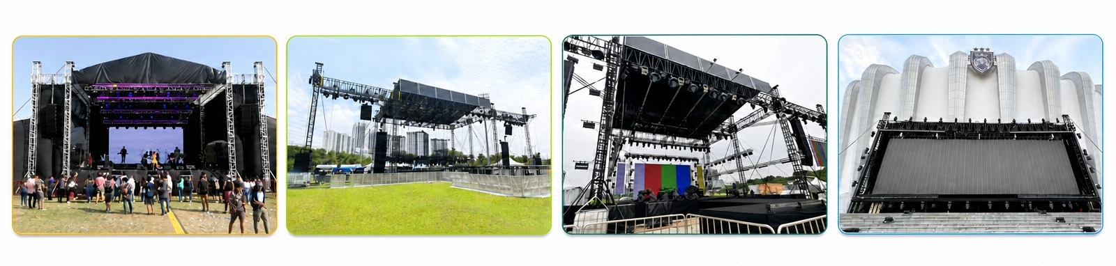
This article focuses specifically on tower components, operation and applications. For a broader overview of complete event structures, read our guide to stage truss systems and how they work.
What Is a Truss Tower System?
|
A truss tower system is a truss structure used to raise and position horizontal truss beams. In a typical configuration, two or more towers are placed around the event area, with truss beams connected around them through movable sleeve blocks.
The term truss tower refers to the complete tower assembly rather than only the vertical truss column. The vertical truss column itself is the truss pillar, which is normally built from several modular truss sections.
The number and layout of the truss towers depend on the structure being created. Two towers may be used for a goalpost truss system, while four or more towers may be required for a rectangular grid or roof structure.
A single tower can also be designed for a dedicated application, such as lifting and supporting a line array speaker system. This is a different configuration from a multi tower system supporting horizontal truss beams. |
 |
Main Components of a Truss Tower System
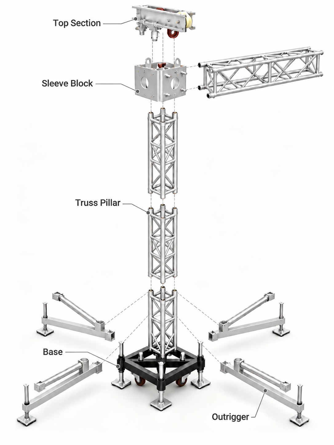
The components included in a tower system vary according to its height, intended application and lifting arrangement. The following parts are commonly found in professional event tower systems.
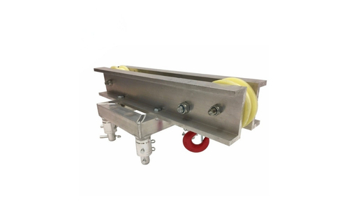
l Top Section
The top section, sometimes referred to as the head block, is installed at the top of the truss pillar. It contains rotating sheaves that guide the hoist load chain over the top of the tower.
The sheaves change the direction in which the chain travels, allowing the hoist to raise or lower the sleeve block and connected truss beam. The top section must be correctly aligned with the hoist, load chain and designated lifting point.
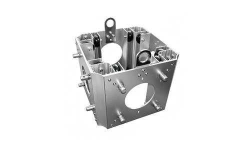
l Sleeve Block
The sleeve block fits around the truss pillar and provides connection points for the horizontal truss beams. It moves vertically along the pillar when the hoist raises or lowers the beam structure.
Guide wheels inside the sleeve block help maintain alignment with the pillar and limit unwanted horizontal movement. The wheels primarily guide the sleeve block and should not be described as the main components carrying the vertical load.
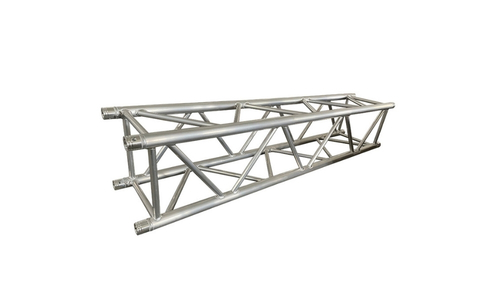
l Truss Pillars
Truss pillars are connected to form the vertical column of the tower. Their modular construction allows different tower heights to be created from compatible standard sections.
The pillar provides the vertical path followed by the sleeve block. The selected section type, connection system and assembled height must follow the technical limitations of the tower design.
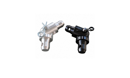
l Tower Hinges
Tower hinges connect the first pillar section to the upper pillar sections. Their pivoting design allows the upper pillar assembly to be prepared near ground level and then swung upward into a vertical position.
This makes it possible to fit the upper pillar sections, top section and hoist before the pillar is raised. Once upright, the pillar connections are completed with the specified pins and R-clips.
l Hoist
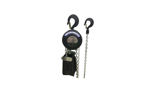
The hoist creates the lifting movement required to raise and lower the truss beam. A specification such as 1T/5m means that the hoist has a rated capacity of one tonne and a chain length of five meters.
Hoist capacity alone does not determine the allowable capacity of the complete system. The limits of the beams, sleeve blocks, top sections, pillars, connections and supporting arrangement must also be considered.
l Sling
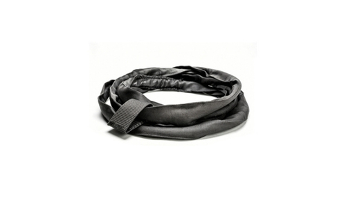
A sling is used as part of the connection between the hoist and truss beam. The sling type, length, and working load limit must match the hoist and the intended lifting arrangement. It must also be protected from sharp edges and other conditions that could cause damage.
l Base
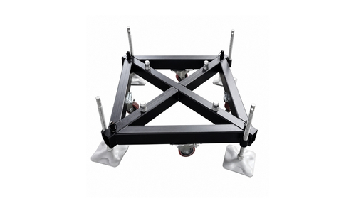
The base connects the bottom of the truss pillar to the lower support structure. It establishes the position of the tower and provides connection points for the first pillar section and outriggers.
The base must match the pillar dimensions and connection system. It must also be placed on a supporting surface suitable for the complete tower configuration.
l Outriggers
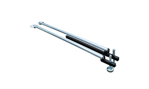
Outriggers extend outward from the base to create a wider support footprint. They help control lateral movement and improve stability during tower erection and use. All outriggers are equipped with adjustable supporting pads. Depending on the design, the outriggers can be adjusted to suit the available installation area.
How Does a Truss Tower System Work?
A truss tower system operates through the coordinated movement of the hoists, top sections and sleeve blocks. These components allow the horizontal truss beams to move along the vertical pillars.
The following explanation describes the general operating principle rather than a detailed installation procedure.
l Truss Beams and Sleeve Blocks
The truss beams are connected to sleeve blocks positioned around the pillars. These connections allow each sleeve block and the connected beam structure to move together.
The beams can remain close to ground level while the structure is prepared. This provides accessible working positions for completing the beam connections and installing approved event equipment before lifting. Once connected, the truss beam structure moves upward or downward with the sleeve blocks.
l Hoists and Top Sections
Each tower uses a hoist to generate the lifting movement. The hoist load chain passes over the rotating sheaves inside the top section. A suitable sling forms part of the connection between the hoist and the designated lifting point. When the hoist is operated, movement of the load chain pulls the sleeve block upward or controls its downward movement.
l Pillars and Guided Movement
The truss pillars provide vertical guide paths for the sleeve blocks. As a sleeve block moves, its guide wheels maintain contact with the pillar and help keep the block aligned. This guidance reduces unwanted sideways movement and helps prevent the sleeve block from binding against the pillar. It also helps the connected truss beam remain correctly positioned relative to the towers during lifting and lowering.
l Coordinated Operation
In a structure with several towers, the hoists must operate in a coordinated manner. The sleeve blocks should remain at similar heights so that the truss beam structure does not become excessively tilted. Poorly coordinated movement can cause the beam structure to tilt, create uneven forces at the lifting points and damage the hoists. The same components control the movement when the beams are lowered. The hoists control the downward travel while the sleeve blocks guide the beam structure along the pillars.
Common Applications of Truss Tower Systems
Truss tower configurations vary according to the event type, equipment layout and site conditions. A broader comparison of truss requirements across concerts, trade shows and outdoor events is available in our event truss guide.
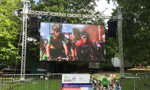
l Goalpost Truss Structures
Two towers can support a straight truss beam to create a goalpost configuration. This type of structure may be used for lighting, banners, entrance structures and smaller event productions. A practical example can be found in our guide to goalpost truss systems for LED wall rigging.
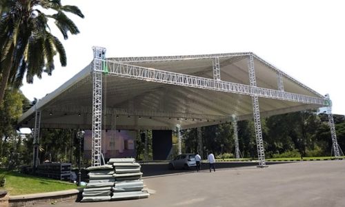
l Temporary Roof Structures
Tower systems can form the vertical lifting points for temporary truss roofs. The roof beams and supporting components are assembled near ground level and raised along the towers.
Outdoor roof systems require project specific engineering because wind, rain, roof coverings and suspended equipment can significantly affect the structure.
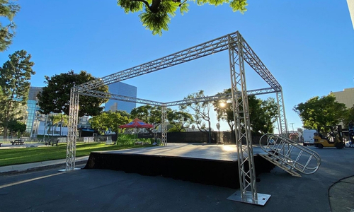
l Exhibition and Event Structures
Truss towers may be used for exhibition booths, product launches and temporary branded environments. The system can support overhead beams used for lighting, signs, screens and decorative elements.
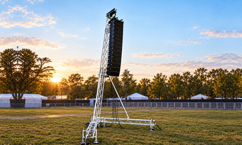
l Line Array Speaker Towers
A single tower can be configured as an independent line array speaker support. It uses a dedicated lifting and stabilization arrangement designed specifically for the speaker system.
Our 6m aluminum line array speaker lifting tower provides an example of this type of configuration.
What Determines the Correct Tower Configuration?
Selecting a tower system involves more than choosing the required height. To develop and assess a suitable configuration, the manufacturer or structural designer normally needs the following project information:
| Project Information | What to Provide | Why It Matters |
| Structure dimensions | Overall length, width, required working height and beam layout | Defines the tower positions and complete structural arrangement |
| Attached equipment | Equipment type, approximate weight and intended position | Equipment position affects the loading arrangement, not only the total weight |
| Tower application | Goalpost structure, rectangular grid, roof structure or line array speaker tower | Different applications require different tower and lifting arrangements |
| Installation environment | Indoor or outdoor use, expected site conditions and attached banners or coverings | Helps identify environmental and stability considerations |
| Available ground area | Installation footprint, surface type, level differences and ground restrictions | Affects the placement of bases, outriggers and stabilization components |
| Stabilization requirements | Permitted use of ballast, anchors or guy wires | Determines whether the proposed tower arrangement is practical for the site |
| Project requirements | Venue restrictions, local regulations and required engineering documentation | Helps identify whether additional review or documentation is required |
ANSI E1.2 covers the design, manufacture and use of aluminum trusses, towers and associated components. It requires the intended configuration and loading conditions to be supported by engineering analysis and manufacturer documentation. The UK Health and Safety Executive also provides guidance for planning and using temporary demountable structures.
Basic Checks Before Use
Before operating a tower system, verify that:
l The configuration follows the approved design
l Bases are correctly positioned and supported
l Outriggers are installed as specified
l Pins and R-clips are fully inserted
l Sleeve blocks move freely and remain aligned
l Hoists, chains and slings have suitable ratings
l Equipment is attached at approved positions
l All lifting points can operate in coordination
* Damaged, deformed or incompatible components should not be used.
Conclusion
A truss tower system allows horizontal truss beams to be prepared near ground level and positioned at the required working height. Its operation depends on compatible sleeve blocks, hoists, top sections, pillars and supporting components working together.
The correct system should be selected according to the complete beam layout, equipment arrangement, site conditions and engineering requirements. Available configurations can be viewed in our tower system category.
FAQ
What is the difference between a truss tower and a truss pillar?
A truss pillar is the assembled vertical column built from modular truss sections. A truss tower is the complete system: pillar, base, outriggers, sleeve block, tower hinges, top section and lifting components. The pillar is one part of the tower rather than another name for the complete assembly.
How many towers are required?
The required number depends on the dimensions, beam layout, equipment weight and location of the lifting points. A straight span may use two towers, while a rectangular grid or roof structure normally requires more.
Can any sleeve block be used with any truss pillar?
The sleeve blocks can be designed as shared components for specified truss combinations. For example, we can customize a sleeve block system for use with 400 × 400 mm truss beams and 290 × 290 mm truss pillars. This two-purpose design allows one sleeve block system to be used with both specified truss combinations, reducing the need to purchase and store separate sleeve blocks for different applications.
Can a single truss tower support a line array speaker?
Yes, when the tower has been designed as a standalone line array support. It requires an appropriate lifting arrangement and a stability design based on the speaker weight, height and site conditions.


 IPv6 network supported
Leave A Message
Scan to Whatsapp :

Hi! Click one of our members below to chat on
 Tel :
Tel : Email :
 English
 Français
 Pусский
 Español
 العربية